Key Takeaways
- Once a sensor is deployed in a groundwater well, access is expensive and retrieval is disruptive. That reality changes how cable needs to be specified. A general-purpose cable nicked during installation can wick moisture through the core for years, degrading insulation resistance and causing readings to drift without any obvious alarm.
- Water-blocking construction is not optional for long-term submersible deployments. Gels, tapes, or swellable materials stop moisture from migrating along the cable core if the jacket is damaged. A nick at installation should not become a sensor failure two years into a decade-long monitoring program.
- Groundwater chemistry varies significantly by site and affects how jacket and insulation materials perform over time. Dissolved minerals, agricultural runoff, industrial contaminants, and naturally occurring compounds all need to be factored into material selection. Assuming universal chemical compatibility is one of the most common specification errors in groundwater cable design.
- Dimensional stability matters as much as electrical performance. Changes in cable length or elasticity over time introduce measurement error into water level and pressure readings. In a monitoring program tracking seasonal fluctuation or long-term aquifer behavior, that drift compounds over years and can lead to incorrect conclusions about aquifer health or pumping thresholds.
- Cable specification at installation follows the system for its entire service life. A partnership that began with a single proof-of-concept for a global water quality monitoring manufacturer grew over fifteen years to encompass more than seven cable designs and twenty assembly families. That kind of expansion happens when the cable performs in the field and the supply relationship earns trust over time.
Groundwater monitoring sensors are often installed hundreds of feet below grade and left in place for years. The cable connecting those sensors to surface instrumentation is not a secondary consideration. It is one of the most failure-prone components in the system, and when it fails, retrieval and replacement are expensive, time-consuming, and disruptive to the data record.
Standard cable is not built for continuous submersion, variable groundwater chemistry, or the mechanical demands of deep well deployment. Custom groundwater monitoring cable is designed specifically for these conditions, giving sensors a stable, reliable signal path for the full life of the monitoring program.
Why Groundwater Monitoring Cable Is Different From Standard Cable
Surface and above-grade cable installations give you options when something goes wrong. You can inspect the run, swap a section, or troubleshoot without major disruption. Groundwater monitoring systems don’t offer that flexibility. Once a sensor assembly is deployed in a well, the cost and complexity of pulling it increases dramatically.
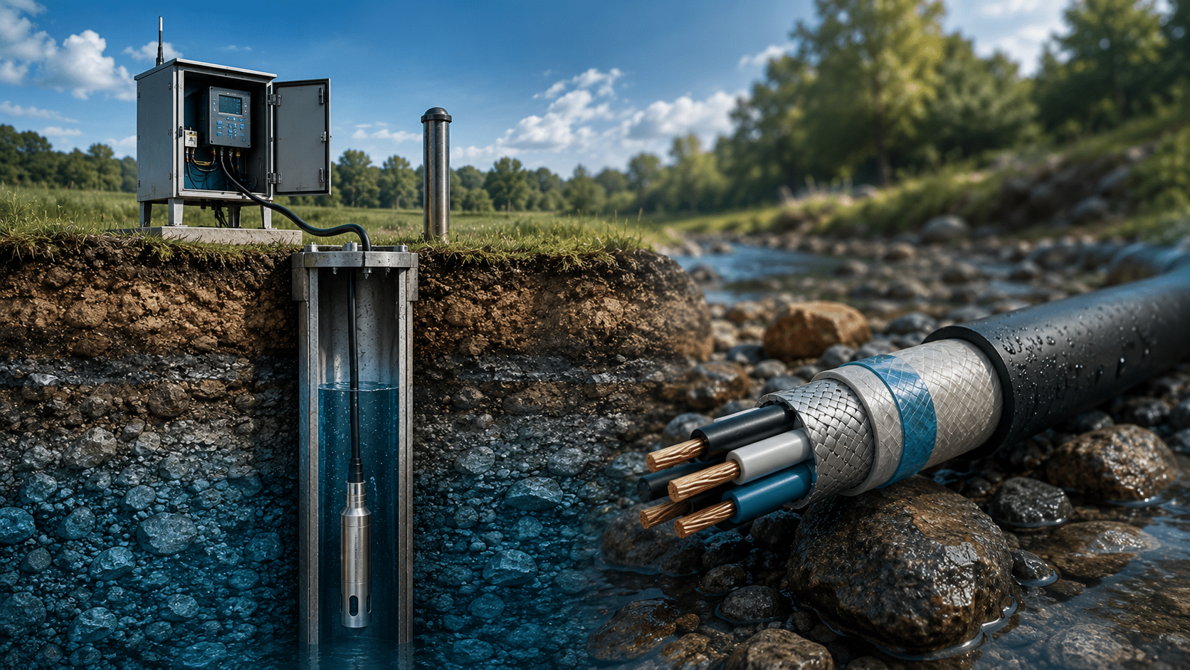
That reality changes how cable needs to be specified. A general-purpose cable without water-blocking can be nicked during installation. Water wicks through the core, insulation resistance degrades, and readings drift without any obvious alarm. By the time the data problem is identified, you may have months of compromised records and a full retrieval on your hands.
Cable engineered for groundwater applications is built around submersion, chemistry, depth, and service life from the start, not adapted from a catalog alternative after the fact.
Core Requirements for Submersible Groundwater Cable
-
Water-Blocking Construction
Water-blocking uses gels, tapes, or swellable materials to stop moisture from migrating along the cable core if the jacket is damaged. In a subsurface installation where inspection is not practical, this is a critical protection layer. A jacket nick at installation should not become a sensor failure two years later.
-
Submersible Compatibility
Materials need to maintain their electrical and mechanical performance under continuous immersion. Not all insulation and jacketing compounds hold up equally at depth or over long exposure periods. The selection depends on expected well depth, hydrostatic pressure, and duration of deployment.
-
Chemical Resistance
Groundwater chemistry varies significantly by site. Dissolved minerals, agricultural runoff, industrial contaminants, and naturally occurring compounds all affect how jacket and insulation materials perform over time. Cable chemistry needs to be matched to site conditions, not assumed to be universal.
-
Long-Term Stability
Electrical properties need to remain within spec over years or decades without access for service. Dimensional stability matters too. Changes in cable length or elasticity over time can introduce measurement error in water level and pressure readings. This is specifically called out in monitoring program documentation as a contributor to drift, not a theoretical concern.
-
Flexible Installation Characteristics
Cables are bent, coiled, and fed through narrow wellheads during deployment. They may be pulled and reinstalled multiple times over the life of a monitoring program. Construction needs to accommodate repeated handling without damaging conductors or insulation.
In practice, these requirements stack on top of each other in ways that are difficult to validate without purpose-built testing. For one long-term water quality monitoring program, we built a dedicated flex test rig to validate cable performance against a 100,000-cycle flex requirement under simulated field conditions before a single assembly shipped. The client’s instruments operate in continuously wet, often corrosive environments. Meeting the flex life requirement and the waterproofing requirement simultaneously required engineering both in parallel, not treating them as separate specifications.
Conductor Selection for Subsurface Signal Reliability
-
01
Stranded vs. Solid Conductors
Stranded conductors handle the repeated bending and movement of deployment and retrieval better than solid conductors. Solid conductors offer more stable signal transmission for low-level analog measurements where dimensional consistency matters. The right choice depends on the sensor type, the measurement resolution required, and how frequently the cable will be handled.
-
02
Tinned Copper for Corrosion Resistance
Sites with variable mineral content or trace contaminants in the groundwater benefit from tinned copper conductors. The tin coating adds a layer of corrosion resistance that bare copper does not provide, extending conductor performance in chemically active environments.
-
03
Conductor Sizing for Depth and Signal Integrity
A sensor deployed hundreds of feet down with a horizontal run back to a data logger needs conductor sizing that accounts for the total circuit length. Undersized conductors introduce resistance that affects signal quality and measurement accuracy. This is a specification input that needs to be calculated for the actual installation geometry, not selected from a generic spec sheet.
How Cable Design Affects Long-Term Data Accuracy
Signal Drift and Measurement Error Over Time
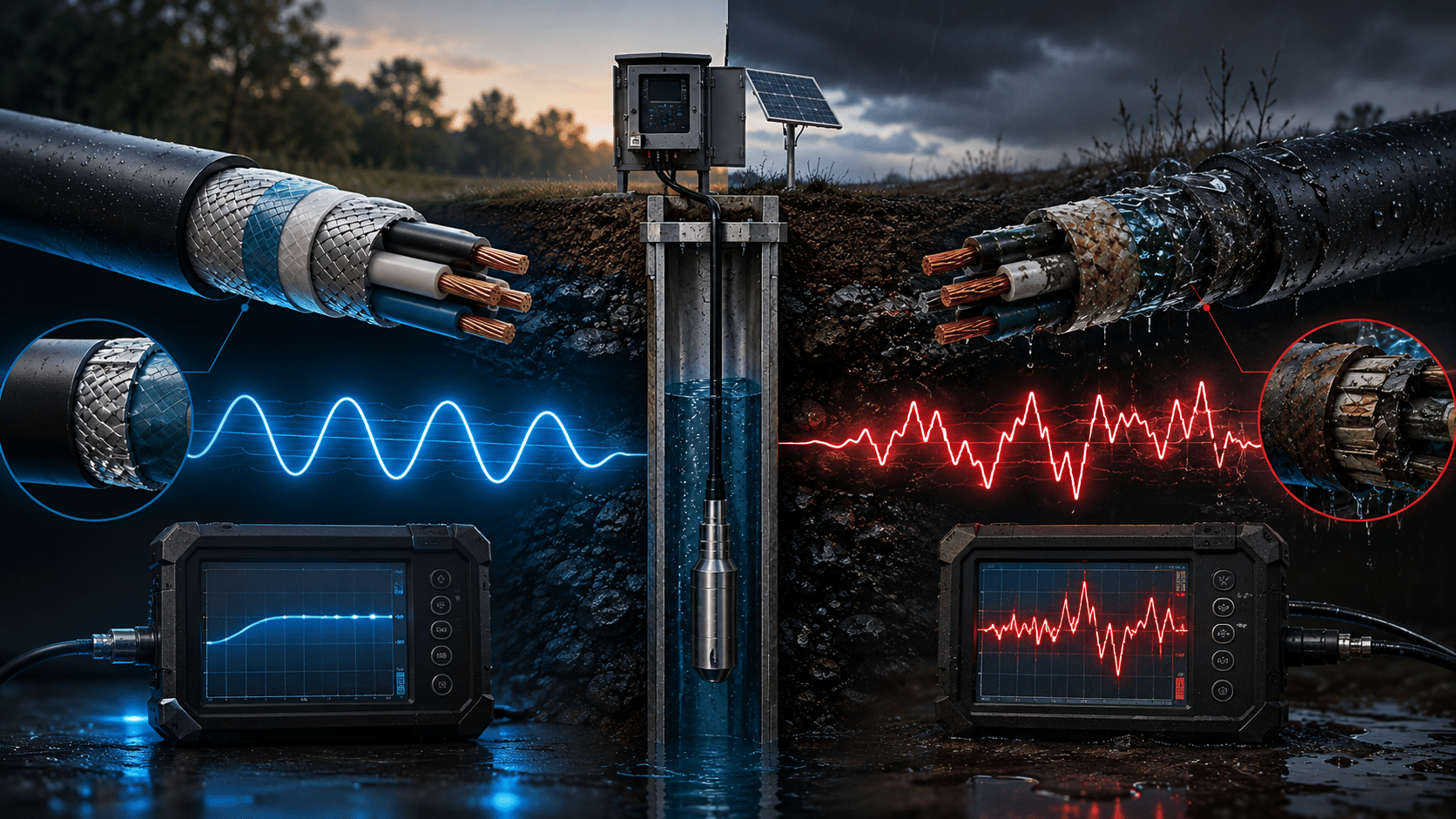
Even small changes in cable characteristics can affect measurements. Insulation resistance degradation, changes in conductor geometry, and moisture ingress all introduce error into water level and pressure readings. In a monitoring program designed to track seasonal fluctuation or long-term aquifer behavior, that drift matters. Small errors compound over time and can lead to incorrect conclusions about aquifer health or pumping thresholds.
Shielding Against Underground EMI
Pumps, motors, and nearby electrical infrastructure generate noise that can affect low-level sensor signals. Proper shielding and grounding keeps that noise out of the signal path. In well networks near agricultural or industrial operations, this is a routine design consideration, not an edge case.
Real-World Scenario: With and Without the Right Cable
Consider a monitoring well network tracking groundwater levels near an agricultural region.
| In a monitoring well network | General-purpose cable | Cable engineered for the well |
|---|---|---|
| Cable construction | No water-blocking, nicked during installation | Water-blocked, chemically resistant, submersible |
| Level and pressure readings | Drift over time and under-report drawdown | Reliably record seasonal fluctuation and drought impact |
| Threshold warning | None; falling levels go unnoticed | Early warning before high-boron groundwater is drawn in |
| Pumping response | Pumps pull deeper into poorer-quality water | Operators adjust pumping to protect crops and supply |
| Outcome | Elevated boron damages crops and mitigation is expensive | Crops and long-term water supply protected |
Connector Integration for Field-Ready Well Installations
Reducing Installation Time at the Wellhead
Groundwater monitoring installations often happen at remote sites with narrow wellheads and limited setup space. Pre-terminated cable assemblies built for submersible sensors reduce the time and complexity of field installation. The cable and sensor arrive ready to deploy, with strain relief and sealing already engineered for the well environment.
Factory-Built Terminations vs. Field Wiring
Field wiring introduces variability. Controlled, factory-built terminations eliminate the inconsistency of on-site assembly under field conditions and reduce the risk of connection failures that are difficult to diagnose once equipment is downhole. For monitoring programs with multiple well sites, that consistency translates directly to more predictable system performance across the network.
Planning for Lifecycle Reliability and Total Cost
Reducing Maintenance Visits and Sensor Downtime
Each unplanned service visit to a remote well site carries real cost. Travel, labor, data gaps, and potential sensor damage during retrieval add up quickly. Cable that is engineered for the installation environment reduces the frequency of those visits and protects the investment in the sensor hardware itself.
Extending System Lifespan Through Proper Cable Specification
Monitoring programs are designed for long service lives. The cable specification decision made at installation follows the system for its entire operating life. Choosing cable built for the actual conditions of the well, the groundwater chemistry, and the expected service duration is the most reliable way to protect data continuity and reduce total ownership cost over a ten or twenty-year monitoring horizon.
What starts as a single cable design for one instrument platform can grow substantially when the engineering foundation is right. A partnership that began with a single proof-of-concept for a global water quality monitoring manufacturer has grown over fifteen years to encompass more than seven cable designs and twenty assembly families across the client’s product line. We also supply raw cable to some of that client’s other contract manufacturers for applications outside our own assembly scope. That kind of expansion happens when the cable performs in the field and the supply relationship earns trust over time.
Supporting Sustainable Groundwater Stewardship
Reliable monitoring data supports better decisions about water use, aquifer management, and land development. When cable is engineered for the realities of the installation, stakeholders can trust what they collect. That confidence supports watershed protection, agricultural water optimization, climate and recharge tracking, infrastructure impact assessment, and long-term environmental compliance.
The quality of those decisions depends on the quality of the data. The quality of the data depends, in part, on the cable carrying it.
Designing Groundwater Monitoring Cable Around Your Application
No two well sites are identical. Effective cable specification for a groundwater monitoring installation requires working from the actual conditions of the project, not a generic starting point.
Key Specification Inputs
Installation Location and Well Depth
Depth determines hydrostatic pressure requirements and conductor sizing. Remote location affects how much serviceability matters in the design.
Expected Groundwater Chemistry
Known or anticipated contaminants, dissolved minerals, and pH levels inform jacket and insulation material selection.
Sensor Requirements and Signal Type
Analog, digital, and power-plus-signal configurations have different conductor and shielding requirements. Measurement resolution affects how much conductor stability matters.
Distance to Surface Instrumentation
Total circuit length from sensor to data logger drives conductor sizing calculations.
Expected Service Life and Maintenance Access
A ten-year program with difficult site access requires different specification decisions than a two-year installation with easy retrieval.
Working with a cable partner experienced in subsurface environmental monitoring ensures the final specification addresses all of these inputs, not just the ones that are easiest to quantify.