Key Takeaways
- Pipeline monitoring cable failures rarely announce themselves as cable problems. What they look like from the control room is a blind spot, a sensor segment that stops reporting, or data gaps in a network designed to have none. By the time the root cause is traced to buried cable, excavation and replacement costs have already exceeded the original cable cost many times over.
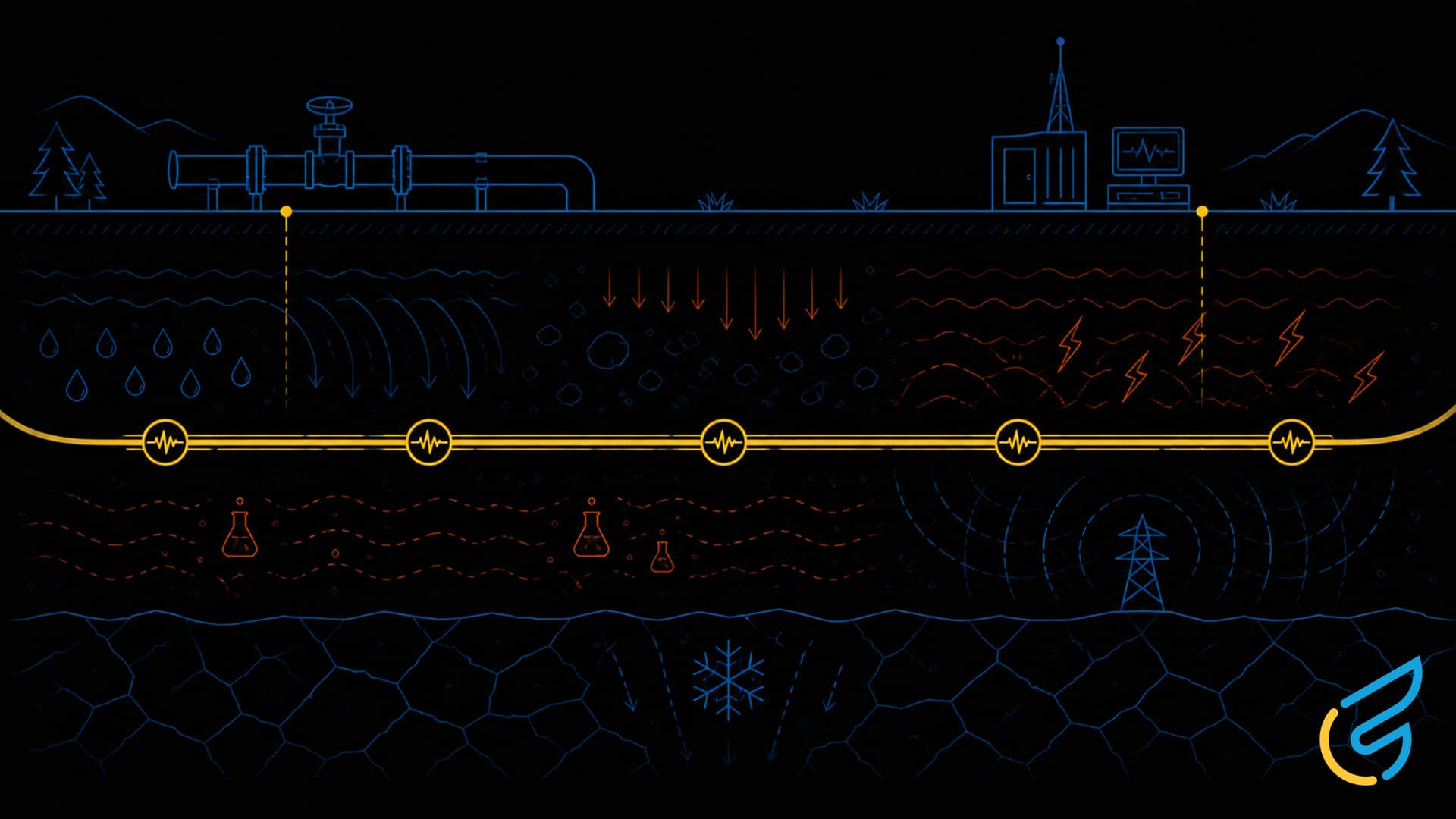
- The most common failure drivers are predictable and preventable: moisture intrusion under sustained ground contact, chemical attack from agricultural or industrial soils along the right-of-way, mechanical stress during installation and backfill, and EMI from pumping stations, power lines, and industrial infrastructure along the corridor.
- Long-distance signal integrity requires low-capacitance cable design. Capacitive loading degrades analog signals over extended runs in ways that conductor sizing alone does not address. This needs to be calculated for the actual circuit geometry of the installation, not estimated from a generic instrumentation cable spec.
- Jacket and armoring specification must match the actual route conditions, not a generic direct burial rating. A corridor crossing agricultural land has different chemical exposure requirements than one crossing industrial land, and routes with variable conditions may need different specifications for different sections.
- Pipeline assets are designed for decades of service. The cable monitoring those assets needs to match that service life. A cable that performs reliably for thirty years costs less over the asset life than a cheaper cable that requires excavation and replacement after fifteen, especially when excavation costs in urban or agricultural land are factored in.
Pipeline monitoring infrastructure is one of the most demanding cable environments in environmental sensing. Cables span miles of varied terrain, buried under soils with different chemical profiles, moisture levels, and mechanical stresses across the route. They sit in the ground for decades without inspection. They carry critical signals from leak detection sensors, pressure transducers, corrosion monitors, and flow meters back to SCADA systems and control rooms that operators depend on for safety, regulatory compliance, and asset integrity.
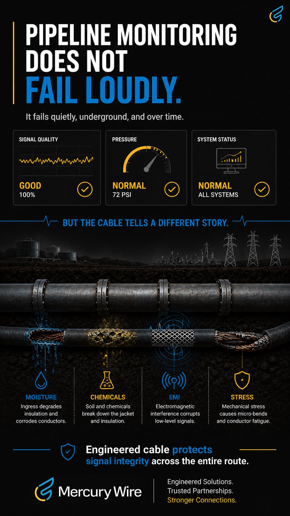
When pipeline monitoring cable fails, it rarely announces itself as a cable problem. What it looks like from the control room is a blind spot. A sensor segment that stops reporting. Data gaps in a monitoring network that was designed to have none. By the time the root cause is traced to the buried cable, the cost of excavation, replacement, and data reconstruction has long exceeded the cost of specifying the cable correctly in the first place.
This post covers what pipeline monitoring cable actually has to survive, how design decisions translate into reliable long-distance signal transmission, and what the specification process should look like for a cable that needs to perform for the life of the asset.
Why Pipeline Monitoring Cable Fails Along the Route
Pipeline monitoring cables fail for reasons that are predictable when you know what the installation environment actually involves. The failure modes are not dramatic. They accumulate slowly over years and express themselves as degraded signal quality, intermittent faults, and eventually complete loss of monitoring coverage in affected segments.
Moisture intrusion is the most common failure driver. Direct burial exposes cable to groundwater, seasonal water table fluctuations, and soil moisture that varies across the route. Standard cable jackets that perform acceptably in dry conduit runs degrade under sustained ground contact. Once moisture reaches the conductor insulation, resistance changes and signal integrity deteriorates.
Chemical attack compounds the moisture problem. Pipeline rights-of-way cross soils with varying chemistry. Agricultural land carries fertilizers and pesticides. Industrial corridors may have hydrocarbon contamination from historical activity. Even natural soil chemistry varies in ways that affect how jacket and insulation materials hold up over a twenty or thirty year service life.
Mechanical stress during installation and backfill causes damage that may not show up immediately. Pull tension, rock contact during trenching, and soil settlement over time all stress cable construction in ways that accumulate into failures years after installation.
EMI from industrial infrastructure along pipeline corridors introduces noise into monitoring signals. Pumping stations, compressor facilities, power lines, and substations all generate electrical interference that corrupts low-level sensor signals when shielding is inadequate for the noise environment.
None of these failure modes are unavoidable. They are all addressable through specification decisions made before the cable goes in the ground.
What Buried Pipeline Monitoring Cable Actually Has to Survive
-
01
Direct Burial and Soil Stress
Direct burial cable needs jacket and insulation materials selected for sustained ground contact, not just resistance to occasional moisture exposure. Soil stress from settlement, frost heave in northern climates, and the weight of backfill material over long service lives places sustained mechanical load on buried cable. Construction that accounts for these stresses maintains integrity where standard cable degrades.
Armoring options including steel tape and wire armor add mechanical protection in installations with rock content, heavy equipment crossings, or unstable soil conditions along the route. The right armoring choice depends on the specific soil and installation conditions, not a generic specification.
-
02
Chemical Exposure Along the Right-of-Way
Chemical resistance needs to be matched to the actual soil and groundwater chemistry along the pipeline corridor, not selected generically. A cable specified for agricultural right-of-way exposure needs different jacket chemistry than one running through an industrial corridor with historical hydrocarbon contamination.
This requires understanding the route before specifying the cable. Soil surveys, historical land use information, and knowledge of pipeline product chemistry in the event of a leak all inform the material selection decision.
-
03
Long-Distance Signal Integrity
Pipeline monitoring runs often cover significant distances between field sensors and SCADA or control room equipment. Run length affects signal quality in ways that accumulate over the full circuit. Low-capacitance cable designs preserve signal quality across extended runs by reducing the capacitive loading that degrades analog signals over distance.
Conductor sizing needs to be calculated for the actual circuit geometry, accounting for the full run length including any above-grade sections at pump stations or block valve locations. Undersized conductors introduce resistance that affects measurement accuracy and can make leak detection thresholds unreliable.
-
04
EMI From Industrial Infrastructure
Pipeline corridors frequently run parallel to power transmission lines, near pump stations, compressor facilities, and industrial operations. These sources generate electrical noise that affects low-level monitoring signals.
Appropriate shielding configuration for the specific noise environment along the route is one of the most consequential design decisions for pipeline monitoring cable. Foil shielding provides baseline protection. Braided shielding adds mechanical durability and coverage for installations with movement or vibration near above-grade equipment. Combination construction delivers maximum rejection in high-interference environments near substations or industrial facilities.
-
05
Mechanical Stress During Installation and Backfill
Installation pulls cable through soil, over rocks, and around bends that place significant tension on the construction. Backfill operations compact soil around buried cable in ways that stress jacket and insulation materials. Above-grade sections at valve stations and pump facilities experience vibration and thermal cycling that accumulate stress at transition points.
Construction that accounts for installation mechanics, not just in-service environmental exposure, performs better over the life of the asset.
Cable Design Priorities for Pipeline Monitoring Infrastructure
-
01
Jacket and Armoring for Direct Burial Performance
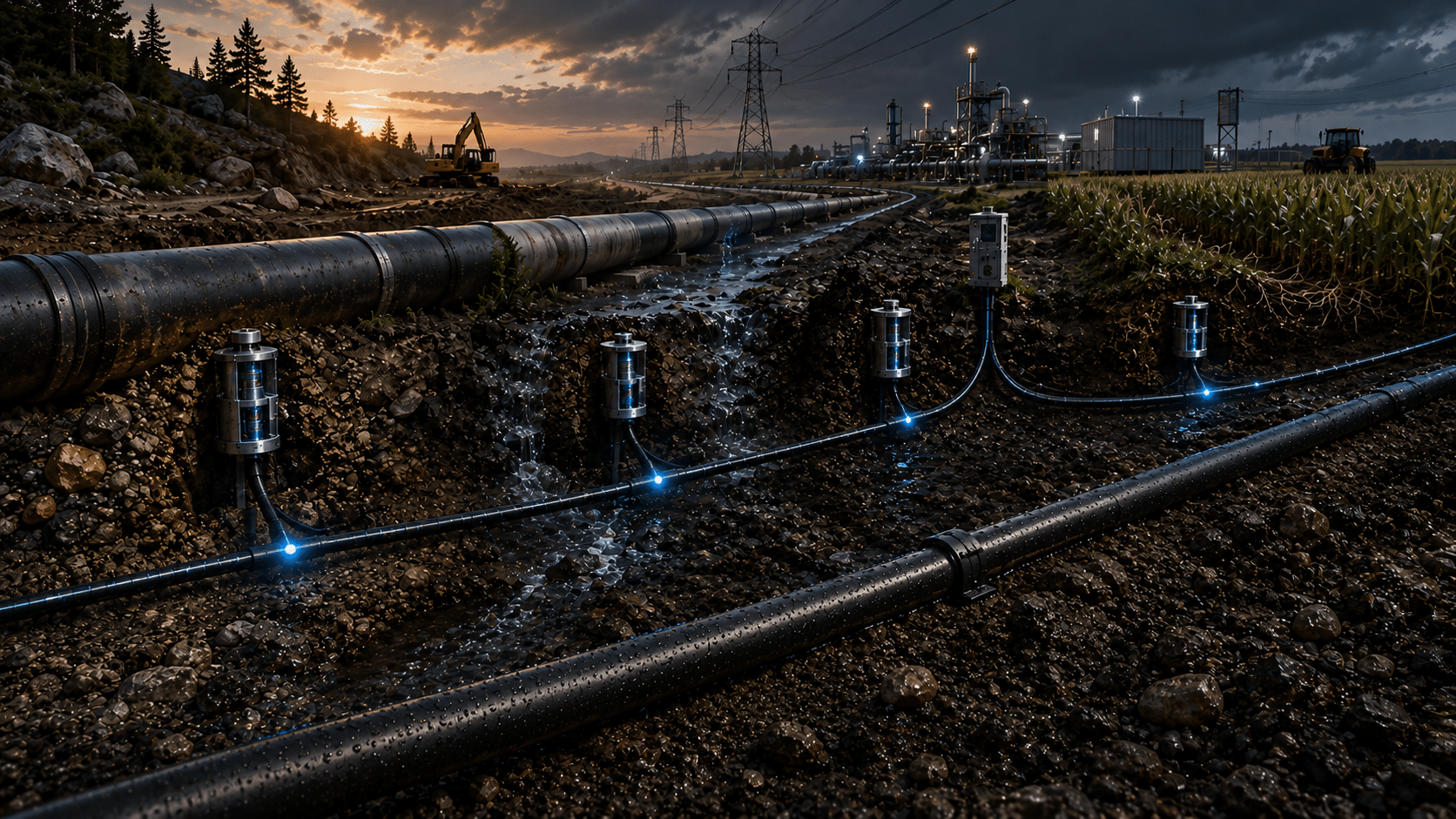
Jacket material selection for direct burial pipeline monitoring cable needs to address sustained ground contact, chemical exposure, and mechanical stress simultaneously. Polyethylene provides strong moisture resistance and chemical stability for most burial environments. High-density polyethylene adds mechanical toughness for installations with abrasive soil conditions. Where mechanical protection requirements exceed what jacketing alone can provide, armored construction adds a layer of defense against rock damage, equipment crossings, and soil movement.
The jacket and armoring specification needs to match the actual conditions of the specific route, not a generic direct burial rating.
-
02
Chemical Resistance Matched to the Corridor
Material selection for chemical resistance requires knowing what the cable will actually be exposed to. A pipeline monitoring cable running through agricultural land for its entire route has different chemical exposure requirements than one crossing industrial land for part of its route and agricultural land for the rest.
Where soil chemistry is uncertain or varies significantly along the route, material selection that provides broader chemical resistance reduces the risk of localized failures in sections with more aggressive conditions.
-
03
Low-Capacitance Design for Long Runs
Low-capacitance cable design preserves signal quality across the extended runs typical of pipeline monitoring installations. This is particularly important for analog sensor signals from pressure transducers, flow meters, and corrosion monitoring systems where measurement accuracy depends on signal fidelity at the receiving end of a long circuit.
Cable geometry, insulation material, and conductor configuration all affect capacitance. These parameters need to be optimized for the specific signal types and run lengths of the installation, not selected from a generic instrumentation cable specification.
-
04
Shielding for Industrial Noise Environments
Shielding selection for pipeline monitoring cable depends on the electromagnetic environment along the specific route. Routes near power transmission infrastructure, industrial facilities, or pump and compressor stations need shielding configurations matched to the interference sources present.
Drain wire continuity along the full cable run is as important as the shielding construction itself. A shielded cable with interrupted or poorly grounded drain wire protection provides substantially less noise rejection than the shielding design suggests.
-
05
Conductor Selection for Distributed Sensor Networks
Pipeline monitoring networks typically distribute sensors across long routes with varying distances to data acquisition equipment. Conductor sizing needs to account for the longest runs in the network, not average run length, to ensure consistent signal quality across all monitoring points.
Stranded conductors handle the mechanical demands of installation and above-grade movement better than solid conductors. Tinned copper adds corrosion resistance in burial environments with aggressive soil chemistry or high moisture content.
Real-World Scenario: Pipeline Leak Detection With and Without the Right Cable
Consider a long-distance water transmission pipeline running through a mix of agricultural land and light industrial areas.
With properly engineered cable: direct-burial, chemically resistant, armored cable with low-capacitance pairs connects distributed pressure and acoustic leak-detection sensors back to a central SCADA system. When a small leak develops near an industrial corridor crossing, sensors detect subtle changes in flow and acoustic signature. Operators identify the location within a few hundred meters, isolate the section, and dispatch a crew before the leak grows. Nearby surface water is protected. Regulatory reporting documents a contained incident with rapid response.
Without the right cable: standard cable with general-purpose PVC jacketing degrades in soils with hydrocarbon contamination from past industrial activity along part of the route. Moisture and chemical attack cause intermittent faults in affected segments. The monitoring system loses reliable data from those sections, leaving operators with blind spots in the network. A leak develops in a previously compromised monitoring zone and goes undetected for weeks. Soil remediation costs, regulatory penalties, and reputational damage follow. The investigation traces the monitoring failure to buried cable that was never specified for the actual soil conditions along the route.
Connector Integration for Remote Pipeline Access Points
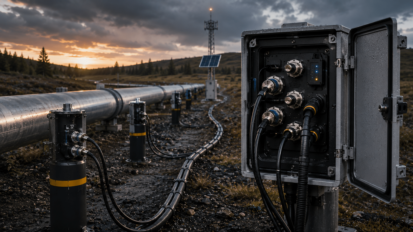
Pipeline monitoring systems include connection points at block valves, pump stations, meter runs, and junction boxes distributed along the route. These access points are often in remote locations with limited setup space and infrequent maintenance windows.
Pre-terminated cable assemblies designed for pipeline monitoring applications reduce installation time and improve connection reliability at each access point. Controlled, factory-built terminations eliminate the variability of field wiring under difficult conditions and reduce the risk of connection failures that create intermittent faults difficult to diagnose in a buried system.
For pipeline operators running monitoring networks across multiple facilities or long routes, consistent factory-built terminations also simplify maintenance and replacement when segments need service. A crew working a remote valve station knows exactly what they’re dealing with rather than troubleshooting field wiring of unknown quality.
Planning Pipeline Monitoring Cable for the Life of the Asset
Pipeline assets are designed for service lives measured in decades. The cable monitoring those assets needs to match that service life, or the monitoring network requires costly replacement and excavation before the pipeline itself needs significant work.
That calculation changes the economics of cable specification substantially. A cable that costs more but performs reliably for thirty years costs less over the asset life than a cable that requires excavation and replacement after fifteen. Excavation costs alone, particularly in urban or agricultural land, can be multiples of the original cable installation cost.
| Consideration | Generic direct-burial cable | Cable specified for the route |
|---|---|---|
| Basis for selection | A generic direct-burial rating from a catalog | The actual soil, chemical, and electromagnetic conditions of the route |
| Reliable service life | Around fifteen years before faults begin to appear | Matches the decades-long service life of the pipeline asset |
| Upfront cable cost | Lower | Higher |
| Mid-life excavation and replacement | Likely, before the pipeline itself needs significant work | Avoided within the asset’s service window |
| Excavation cost exposure | Can run multiples of the original install cost in urban or agricultural land | Not incurred mid-life |
| Total cost over the asset life | Higher once excavation and replacement are counted | Lower |
The right way to approach this calculation is to specify cable for the actual service life of the monitoring program, the actual soil and chemical conditions of the route, and the actual electromagnetic environment the cable will operate in. That requires working from the specific conditions of the installation rather than from a generic specification.
At Mercury Wire, every pipeline monitoring cable program starts with a thorough understanding of the application and the environment, not a catalog selection. Our value stream teams work directly with your engineers from initial specification through production, with dedicated capacity and inventory management aligned to your program timeline. That process produces cable built for the specific conditions of your route, not adapted from a standard product after the fact.
Designing Pipeline Monitoring Cable Around Your Route
No two pipeline routes have identical monitoring cable requirements. Effective specification starts from the actual conditions of the installation.
Key Specification Inputs
Route Characteristics and Installation Method
Direct burial, conduit, above-grade sections at facilities, and river or road crossings each present different mechanical and environmental requirements. The installation method across the full route drives construction decisions.
Soil Conditions and Chemical Exposure Profile
Soil type, moisture level, groundwater chemistry, and historical land use along the corridor inform jacket and insulation material selection. Routes with variable conditions across their length may require different specifications for different sections.
Sensor Types and Communication Protocols
Pressure, flow, acoustic, corrosion, and temperature sensors each have different signal characteristics and conductor requirements. Communication protocol, whether analog, digital, or fieldbus, affects shielding and cable geometry decisions.
Run Length and Signal Architecture
Total circuit length from field sensor to data acquisition equipment drives conductor sizing and low-capacitance design requirements. Network architecture, whether star, daisy-chain, or distributed, affects how those requirements vary across the installation.
Expected Service Life and Access Constraints
A thirty-year monitoring program along a route with difficult excavation access requires different specification decisions than a ten-year program with easy maintenance access. Service life and access constraints together determine how much margin to build into the specification.
Working with a cable partner experienced in pipeline monitoring and long-distance buried instrumentation ensures the final specification addresses the actual conditions of the route across its full service life.